Sunday, May 1, 2011

Cannon FIRE!

A cannon requires 3 steps in order to fire successfully.

1. The first step is Preparation:
Placing a cartridge of black powder, which is gunpowder, made from paper, flannel or wool. How much powder used was based on the distance to the target, the size of the cannon and what type of projectile is used. To get the cartridge to the bottom of the tube, breach with a rammer.


2. Ignition:

  • A friction primer is used to ignite the black powder that is in the tube. The friction primer consists of a hollow tube that fits into the vent hole. At its top there is an opening through which a serrated wire can be inserted. The wire has a loop on it through which a lanyard, or rope, is attached.

    When it is time to fire the cannon the rope on the friction primer is pulled. The serrated wire creates enough heat from friction to ignite the black powder that is in the primer tube. This fire ignites the black powder in the breech. The explosion that results from the breech powder being ignited propels the projectile out the end of the tube.


3.
Aiming
  • Aiming the cannon is done by pointing the piece, the cannon, with a breech sight for the up and down elevation and the cannon was moved left or right for lateral positioning.


Thursday, April 14, 2011

Pulley Cart


In physic class, we get to play around with the pulley carts with 3 metal coins inside them and also a ticker-tape timer. The purpose of this lab is to show and prove the relationships between acceleration, total force and the mass.

The metal pieces are tied to the strings to act as the force that pulls the cart across the table until the distance traveled equals the height of the table. At the same time, the ticker-tape is used to record the pattern of acceleration of the different trials.

After the entire experiment, 5 different tapes are generated from the timer and are used for later analysis and calculations.


Data for 6 Scenarios:


1) acceleration vs. force 1

d1=0.008 m d2=0.03 m dt=0.24m
t=1/30 s t=1/30 s a=1.6m/s ^2
v1= 0.24 m/s v2=0.9m/s

2) acceleration vs. force 2

d1=0.029m d2=0.09 m dt=0.58m
t=1/30 s t=1/30 s a= 5.6 m/s ^2
v1= 0.87 m/s v2=2.7m/s


3) acceleration vs. force 3

d1=0.035m d2=0.073 m dt=0.35m
t=1/30 s t=1/30 s a= 5.28 m/s ^2
v1= 1.05 m/s v2=2.19m/s

4) acceleration vs.mass 1

d1=0.008 m d2=0.03 m dt=0.24m
t=1/30 s t=1/30 s a=1.6m/s ^2
v1= 0.24 m/s v2=0.9m/s

5) acceleration vs. mass 2

d1=0.065m d2=0.1m dt=5.4m
t=1/30 s t=1/30 s a= 5.2 m/s ^2
v1=1.95 m/s v2=3.06m/s


6) acceleration vs. mass 3

d1=0.055m d2=0.13 m dt=0.53m
t=1/30 s t=1/30 s a= 11.8m/s ^2
v1=1.65 m/s v2= 3.9 m/s


Building Our Own TALLEST Structure

In Physics class, we were assigned to build the "tallest structure" with simply just newspaper and tape. The point of this little activity was to get an understanding of how tall buildings can stand at such extreme heights, and also for us to know more about the center of gravity.

The structure we built in class was not carefully planned out before, and we started to building the structure off scratch without any clues on how everything worked. We made the structure itself first, and we tried to make a base that could possibly make it stand. However, we made a fatal mistake on the base, because it barely had any weights in it, and therefore it could not become the center of gravity and it could not stand in the end.


Tuesday, April 12, 2011

Tallest Structure!

The design of Burj Khalifa is derived from patterning systems embodied in Islamic Architecture.


The tower is composed of three elements arranged around a central core.

As the tower rises from the flat desert base,setbacks occur at each element in an upward spiralling pattern, decreasing the cross section of the tower as it reaches toward the sky.

A setback, sometimes called step-back, is a step-like recession in a wall.
A series of five setbacks, each of decreasing size, result in the pyramid being much narrower at its peak than at its base.

To support the unprecedented height of the building, the engineers developed a new structural system called the buttressed core, which consists of a hexagonal core reinforced by three buttresses that form the ‘Y' shape. This structural system enables the building to support itself laterally and keeps it from twisting.

The building rises to the heavens in several separate stalks, which top out unevenly around the central spire. This somewhat odd-looking design deflects the wind around the structure and prevents it from forming organized whirlpools of air current, or vortices, that would rock the tower from side to side and could even damage the building.
The primary structural system of Burj Khalifa is reinforced concrete. Over 45,000 m3 (58,900 cu yd) of concrete, weighing more than 110,000 tonnes (120,000 ST; 110,000 LT) were used to construct the concrete and steel foundation, which features 192 piles, with each pile is 1.5 metre diameter x 43 metre long buried more than 50 m (164 ft) deep. Burj Khalifa's construction used 330,000 m3 (431,600 cu yd) of concrete and 55,000 tonnes of steel rebar, and construction took 22 million man-hours. A high density, low permeability concrete was used in the foundations of Burj Khalifa. A cathodic protection system under the mat is used to minimize any detrimental effects from corrosive chemicals in local ground water.

Special mixes of concrete are made to withstand the extreme pressures of the massive building weight; as is typical with reinforced concrete construction, each batch of concrete used was tested to ensure it could withstand certain pressures.

Tuesday, March 29, 2011

Aerodynamics!!

What is aerodynamics? Aerodynamics is the study of forces and the resulting motion of objects through the air. Aerodynamics is involved in the flight of an airplane, the curve of a baseball pitch, and a kite flying in the sky. Because the object travels through air, its reaction to the air must also be considered when dealing with aerodynamics. The basic laws of motion and gas properties are also considered in aerodynamics.

There are three basic laws of aerodynamics (laws of conservation).

The first is the law of continuity. It states that if a certain mass of fluid enters a volume, it must either exit the volume or change the mass inside the volume. The second is the conservation of momentum. It states that force is equal to the time derivative of momentum. The final law is the conservation of energy. It states that energy can be converted into a variety of forms, however the total energy in a given system remains constant.

There are three forces that act on a glider, and four forces that act on a powered airplane are all covered in aerodynamics.

A glider is a common type of aircraft that has no engine. There are three forces that act on a glider: lift, drag and weight.

Lift is the force that opposes the aircraft’s weight, which helps the aircraft stay aloft. Lift is perpendicular to the flight direction. Drag is the mechanical, aerodynamic force that opposes the aircraft’s motion through the air. Air resistance is often a great contributer to drag. Weight is the force of gravity pulling down on an object towards the Earth.


Gliders generate its initial velocity by being thrown or having a powered aircraft drag the glider to a higher altitude, giving it a higher potential energy that can be converted to kinetic energy. Pockets of air that are rising faster than the glider is descending help keep the glider aloft. The rising air are called updrafts, and can be found where thermal energy is released.

The distance between the front of to the back of the aircraft’s wing is called the chord. The distance from one wingtip to the other is called the wingspan. The ratio of an aircraft’s wingspan to its average chord distance is called the aspect ratio of wings. A successful glider often uses a high aspect ratio of wings.

A powered aircraft, such as an airplane, as an additional force acting upon it. This force is called thrust. Thrust is a propulsive force created by engines that is used to overcome drag.


Sunday, March 27, 2011

Kinematics Word Problems!

CLICK THE IMAGES TO ENLARGE!


Actual Graphs Obtained From the Lab!!!

CLICK ON THE IMAGES TO ENLARGE!


Distance Vs. Time Graph (1)


Velocity Vs. Time Graph (1)


Velocity Vs. Time Graph (2)


Distance Vs. Time Graph (2)


Distance Vs. Time Graph (3)


Wednesday, March 9, 2011

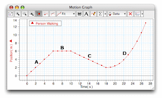
Walking the Graph

In physics class, as usual we got to do something different and interesting. This time, we got a chance to walk the graph!

The activity was to make us learn a bit about kinematics which was simply just how things move. There was a motion sensor, which was connected to the computer with the software that collected how you moved.

There were 5 graphs/motion patterns that we had to walk. There were time vs. distance graphs, and time vs. velocity graphs. In my opinion, the distance/time graph was a lot easier to walk than the velocity ones because it just involves walking towards the sensor and away. However in the velocity graph, it was somewhat challenging. We had to control our speed as we walked, and if a small mistake was made, the graph was messed up.

After MANY trials, we finally got a pattern that SOMEWHAT matches the original graph, and we got to mess around with the stuff.
From this activity, we learned the basic pattern of the motions of distance vs. time and distance vs. velocity.

Wednesday, February 23, 2011

Right Hand Rule #1 & #2

Right hand rule #1 (conductors):

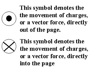
Thumb of right hand points in direction of conventional current flow, fingers point in direction of circular magnetic field around conductor.


Right hand rule #2 (coil):
Curled fingers of right hand point in direction of conventional current flow, thumb points in direction of magnetic field around conductor.


Wednesday, February 16, 2011

Concept Map + Ten Things Must Know

In physics class today, we did something called CONCEPT MAP on electricity unit. It is helpful to visual learners because all the parts of the units are grouped with relations to one another. However, I personally find the concept very confusing and not easy to follow along, and I would study better in other ways.

Anyways. here are some photos taken in class today:


Our own map and other groups' :D


10 Things WE MUST KNOW :


1) Current : rate of flow measured in coulombs per second (amperes) by an ammeter connected in series.

2) Electric Charge: measured in coulombs where 1C =6.24 X 10^ 18 electrons.
1 electron has a charge of 1.60 X 10^-19 C.

3) Series Circuit: charge flows along one path .

4) Parallel Circuit: charge flows along two or more paths.

5) Ohm's law: R=V/I V=IR I =V/R

6) Conventional Current/ Electron Flow: flow of charge from positive terminal to negative terminal for conventional, and from negative to positive for e- flow.

7) Kirchhoff's Law:

For Series:

Current:
It = I1 = I2 = I 3...=In

Potential Difference:
Vt = V1 + V2 + V 3...+Vn

Resistance:
Rt =R1 + R2 + R 3...+Rn


For Parallel Circuit:

Current:
It = I1 +I2 + I 3...+In

Potential Difference:
Vt = V1 =V2 =V 3...=Vn

Resistance:
1/Rt =1/R1 + 1/R2 + 1/R 3...+1/Rn

8) Power : rate at which work is done. P=VI or P= E/t

9) Energy: work, in Joules. E= Pt, E=VQ or E =VIt

10) Potential difference = voltage drop across two given points in a circuit. V=P/I. Measures by voltmeter which is connected in parallel.


Thursday, February 10, 2011

Ohm Vs. Kirchhoff's Law !!

As learned in class, the Ohm law says that the current that goes through a conductor between two give points is directly proportional to the potential difference or the voltage. The current is inversely proportional to the resistance. Given the triangle :


We can figure out from this triangle relationship of ohm's law that :

V= IR
I = V/R
R= V/I


Kirchhoff's Law is based on two equalities that deal with the conservation of charge and energy in the circuits.
Figure 1(a) (circuit4.png)Figure 1(b) (circuit4a.png)

For Series Circuit:

Current:
It = I1 = I2 = I 3...=In

Potential Difference:
Vt = V1 + V2 + V 3...+Vn

Resistance:
Rt =R1 + R2 + R 3...+Rn


For Parallel Circuit:

Current:
It = I1 +I2 + I 3...+In

Potential Difference:
Vt = V1 =V2 =V 3...=Vn

Resistance:
1/Rt =1/R1 + 1/R2 + 1/R 3...+1/Rn


Tuesday, February 8, 2011

Top Roller Coasters!

I've found some really interesting roller coasters on the website recently, and I would really like to share the pictures.


1. Voyage, Holiday World


Roller coaster enthusiasts from all over the WORLD voted the Voyage the number one wooden roller coaster on the planet for four consecutive years.

Features:
Most dramatic drops on The Voyage measure 154 feet (66-degree angle of descent), 107 feet (51-degree angle), and 100 feet (50.5-degree angle).

2. El Toro, Six Flags Great Adventure

El Toro features the steepest drop of any wooden roller coaster in the country at a record-breaking 76 degrees. It combines all the best features of wooden coasters with the smooth speed of their steel counterparts. One can experience the weightlessness with nine separate airtime chances.


3. Bizarro, Six Flags New England


The best steel coaster for the fifth time. It takes into another dimension with fog and fiery flame effects timed JUST perfectly with heart-pumping audio for an incredible ride.


Monday, February 7, 2011

The Battery Circuit !!! Electron Flow Vs. Conventional

In Physics class today, we discussed about two things that seem like the exact same things, but in fact they are the direct opposite-conventional current flow and electron flow.
Electron flow is simply the movement of electrons through a circuit, and conventional current is the movement of the positive charge. As you can see from the following diagram of a battery circuit, it has a battery (cell), an open switch, a load (light bulb) and the arrows showing the directions of the movements. In conventional current flow, it is said to be that the electricity moves from the positive electrode of the cell through the circuit to the negative end ( +----> -).
For electron flow, the electrons are moving from the negative end through the circuit to the positive side (- -----> +).


Saturday, February 5, 2011

The Energy Ball Experience

On Friday, we had our first official physics class with Mr. Chung. The reason that I looked forward to this class was because the teacher is humorous and we could play around with different and interesting "toys" instead of doing textbook work.
We got to play around with very "expensive" pingpong balls that he called the Energy Balls. The energy ball was made of a circuit board with a light bulb that could flash and a buzzer that could make noises. The circuit board was connected to two metal pieces by different wires, and in order for the light bulb and the buzzer to work, both metals had to be touched by conductors like our fingers. When the metals were touched by two different people each with one finger and without them touching each other, the energy ball did not work. This was because it was not a complete series circuit.

When the whole class was given the task to make one ball light up and the other one off while touching one another, the class formed another type of circuit called the parallel circuit. This time there were two resistors, and the electricity had several paths that it could travel. Instead of forming a circle like the series circuit, there was a "line" that cut the circle in half. There were two switches, one on each end. If one end "disconnected", that relevant energy ball would not light up while the one on the other side would still work.

The major difference between a series circuit and a parallel circuit is the way the components (in this case the energy balls and our hands) are connected. In a series circuit, there is only one path for the flow of electricity. For example, Christmas tree lights, if one part of the path is damaged, the rest of the light would not function. In a parallel circuit, there are more than one path of current flow, and if one part of the circuit is obstructed, the current can find other paths.

Series Circuit:

Parallel Circuit:


The energy ball does not work on certain individuals is probably due to the calluses on the palms of their hands. The calluses most likely resists the flow of electricity, therefore when in touch with the metal pieces, the calluses act like insulators which prevents the energy ball from lighting up.